Test Relay with Voltmeter: Electrician’s Guide
A relay is a critical electrical component that acts as an automated switch, controlling high-power circuits with low-power signals. Whether you’re troubleshooting HVAC systems, automotive electrical problems, or home automation circuits, knowing how to check a relay with a voltmeter is an essential skill for any DIY enthusiast or professional electrician. This comprehensive guide walks you through the testing process, safety protocols, and diagnostic techniques to accurately determine if your relay is functioning properly.
Relays appear in countless applications throughout modern homes and vehicles. When a relay fails, entire systems can malfunction—from air conditioning units to security systems to vehicle fuel pumps. Rather than replacing components blindly, a systematic voltage test reveals exactly what’s happening inside the relay’s switching mechanism. With just a basic voltmeter and proper safety procedures, you can diagnose relay problems quickly and confidently.
Understanding Relay Basics and Function
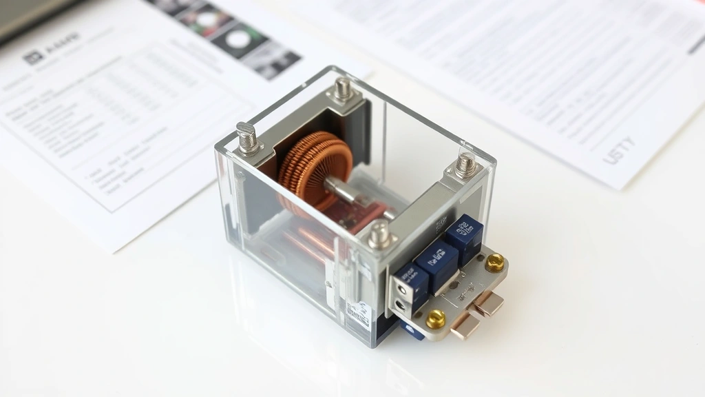
A relay consists of an electromagnet (coil), an armature, and switching contacts. When voltage is applied to the coil, it creates a magnetic field that pulls the armature, which mechanically moves the contacts to complete or break a circuit. This allows a small control signal to switch a much larger power circuit—a fundamental principle in electrical engineering.
Relays come in several varieties: single-pole single-throw (SPST), single-pole double-throw (SPDT), double-pole single-throw (DPST), and double-pole double-throw (DPDT). Each configuration handles different switching scenarios. Understanding your relay’s type is crucial because the pin configuration and testing points vary significantly. Most relays have four to eight pins: coil pins (typically pins 1 and 2) and contact pins (the remaining pins that carry the load current).
The coil voltage rating is critical—common ratings include 5V, 12V, 24V, and 120V AC or DC. If you apply incorrect voltage, you risk damaging the relay or getting inaccurate readings. Always verify the relay’s specifications before testing. You can find this information on the relay’s casing, the device’s schematic, or the manufacturer’s datasheet.

Safety Precautions Before Testing
Electrical work carries inherent risks. Before you begin testing any relay, ensure the power is completely disconnected from the circuit. Even when working with low-voltage circuits, proper safety prevents accidents and equipment damage. Always wear safety glasses and keep one hand in your pocket when testing circuits—this reduces the risk of current flowing across your chest if accidental contact occurs.
Use proper lockout/tagout procedures in professional settings. Place a padlock on the main breaker and attach a warning tag explaining that work is in progress. This prevents someone else from accidentally restoring power while you’re testing. In home environments, simply switch off the relevant breaker and verify it’s off using a non-contact voltage tester before beginning work.
Never test relays on live circuits unless absolutely necessary, and only if you’re trained and equipped to do so. Even then, use extreme caution. Your voltmeter should be in good working condition with intact insulation and properly functioning leads. Damaged testing equipment can cause electrocution or provide false readings that lead to dangerous mistakes.
Consult local electrical codes and standards before performing any electrical work. Many jurisdictions require licensed electricians for certain tasks. When in doubt, hire a professional—your safety is worth the cost.
Tools and Equipment You’ll Need
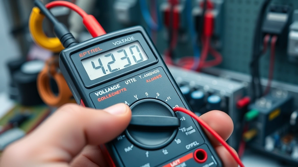
A digital multimeter (which functions as a voltmeter) is your primary tool. Look for a meter rated for the voltage you’re testing. For household circuits, a meter rated for at least 600V is appropriate. The meter should have clear, easy-to-read displays and reliable continuity testing capabilities. Analog voltmeters work too, though digital versions provide more precise readings and are generally safer for modern electronics.
Beyond the voltmeter, gather these items: insulated screwdrivers (flathead and Phillips), needle-nose pliers, wire strippers, and a flashlight or headlamp for visibility in tight spaces. Keep a clipboard handy to document readings—this helps identify patterns and supports troubleshooting logic. A relay schematic or pinout diagram specific to your relay model is invaluable; download it from the manufacturer’s website or find it in the device’s manual.
Consider acquiring a relay test socket or relay puller if you work frequently with relays. These specialized tools make removal and reinstallation safer and easier, reducing the risk of bent pins or damaged sockets. A multimeter with capacitance testing can help diagnose relay coil problems more thoroughly, though basic voltage testing often suffices.
Step-by-Step Testing Procedure
Step 1: Prepare the Circuit — Power down the entire system. Use your non-contact voltage tester to confirm the circuit is de-energized. Test multiple points to ensure safety. Document the relay’s location, model number, and pin configuration before disconnecting anything.
Step 2: Locate the Relay — Relays in homes typically appear in HVAC units, water heaters, garage door openers, security systems, and electrical panels. In vehicles, check the fuse box, engine bay, or under-dash locations. Consult the manual for exact placement. Take photos before disassembly to aid reassembly.
Step 3: Identify Coil and Contact Pins — Using the relay’s pinout diagram, identify which pins are the coil (input) and which are the contacts (output). Coil pins are usually labeled 1 and 2, or A1 and A2. Contact pins vary by relay type. Write this down clearly.
Step 4: Test Coil Resistance — Set your multimeter to resistance (ohms). Place the probes across the coil pins. A good relay coil typically reads between 50 and 1000 ohms, depending on the model. Zero ohms suggests a short circuit; infinite resistance indicates an open coil. Both conditions mean the relay is faulty. Record the reading.
Step 5: Apply Power to the Coil — With the circuit still de-energized, carefully apply the correct voltage to the coil pins using a power supply or battery (matching the relay’s rated voltage). You should hear a distinct clicking sound as the armature engages. If there’s no click, the relay likely won’t function.
Step 6: Test Contact Continuity Unpowered — Set your multimeter to continuity or resistance. With no power applied to the coil, test the normally-closed (NC) contacts—they should show continuity (low resistance or a beep). Normally-open (NO) contacts should show no continuity (infinite resistance or no beep). This confirms the relay’s resting state.
Step 7: Test Contact Continuity Powered — Apply power to the coil again while monitoring the contact pins with your voltmeter. The normally-open contacts should now show continuity, while normally-closed contacts should show no continuity. This proves the relay’s switching mechanism works under load.
Step 8: Measure Coil Voltage Drop — With power applied to the coil, measure the actual voltage across the coil pins using your voltmeter. It should match the relay’s rated voltage (or be very close—within 10% is typically acceptable). Low voltage indicates a weak power supply or circuit resistance issues.
Step 9: Document Your Findings — Create a clear record: coil resistance reading, audible click present/absent, contact continuity before power, contact continuity under power, voltage measurements. This documentation helps you or a technician understand what’s happening and plan repairs.
Interpreting Voltmeter Readings
Understanding what your voltmeter tells you is just as important as taking measurements. When testing coil voltage, the reading should be within 10% of the rated voltage. If you’re applying 12V to a 12V relay but the voltmeter reads only 10V, the coil may not have enough magnetic force to pull the armature reliably. This causes intermittent failures—the relay sometimes works, sometimes doesn’t.
If the voltmeter reads 0V across the coil pins while power is supposedly applied, check your meter first (test it on a known live circuit). If the meter works correctly, the problem lies in your power supply connection or the circuit feeding the relay. Verify all connections are tight and the power source is functioning.
Contact voltage readings should be nearly 0V when contacts are closed (conducting). If you read significant voltage across closed contacts, they’re not making good connection—corrosion, pitting, or mechanical failure is preventing proper contact. The contacts should show full circuit voltage when open (not conducting).
When testing with AC voltage, your meter should display a stable reading. Fluctuating readings suggest an unstable power source or a failing relay coil that can’t maintain consistent magnetic pull. Document these fluctuations as they indicate intermittent operation issues.
Common Relay Problems and Solutions
No Coil Voltage — If your voltmeter shows 0V across the coil, check that power is actually reaching the relay socket. Test the power supply independently. Verify all wire connections are secure. Look for blown fuses or tripped breakers in the control circuit. This is often the most common issue and usually the easiest to fix.
Coil Resistance Too High — When resistance exceeds the normal range (typically 50-1000 ohms depending on the relay), the coil is failing. High resistance means the electromagnet won’t generate sufficient magnetic force. The relay must be replaced. Don’t attempt to repair the coil itself—it’s not economical and rarely successful.
Zero Ohms (Short Circuit) — If your resistance test shows 0 ohms across the coil, current is flowing freely through a short. This will blow fuses or trip breakers. Replace the relay immediately. Don’t apply power to a shorted coil as it can overheat and cause fires.
Contacts Won’t Close — If the contacts show no continuity even when power is applied to the coil, the mechanical switching mechanism has failed. The armature may be stuck due to corrosion or debris. Try gently tapping the relay (with power removed) to dislodge stuck parts. If that fails, replacement is necessary.
Contacts Won’t Open — Stuck closed contacts indicate mechanical failure or welded contacts from excessive current. This is dangerous as the relay can’t stop current flow. Replace immediately and investigate what caused the contacts to weld (usually excessive load current or a short circuit).
Intermittent Operation — If your voltmeter readings fluctuate or the relay works inconsistently, several issues could be responsible: low coil voltage, corroded contacts, loose connections, or a failing power supply. Test all connections, verify voltage stability, and consider replacing the relay if no connection issues are found.
Relay Testing in Different Applications
HVAC Systems — Most air conditioning and heating systems use relays to control compressors, fan motors, and heating elements. When your AC won’t start, a failed relay is often the culprit. These relays typically operate on 24V control circuits. Test the 24V transformer output, then test the relay coil voltage. If 24V reaches the transformer but the relay shows 0V, the control circuit has an issue. If the relay gets proper voltage but won’t click, it’s failed.
Water Heaters and Boilers — Electric water heaters use relays or contactors to switch high-amperage heating elements. These devices demand precise testing because they handle substantial current. Test the control voltage (usually 24V or 120V) and verify the relay clicks when energized. Measure voltage across the heating element contacts to confirm they’re switching properly. Always ensure the unit is completely de-energized before testing.
Security Systems — Alarm systems use relays to control door locks, siren circuits, and notification devices. These low-voltage systems (typically 12V) require careful testing because the control circuits are sensitive. Use your voltmeter gently on these circuits—excessive probing can damage sensitive electronics. Test relay coils at 12V and verify contact closure when armed.
Vehicle Electrical Systems — Automotive relays control fuel pumps, starter motors, headlights, and numerous other functions. Car repair projects often involve relay testing. Most automotive relays run on 12V DC. Test them with your battery as the power source. Listen carefully for the click—it’s often quieter than industrial relays. Check that the relay socket isn’t corroded; oxidation is common in vehicles and prevents proper contact.
Home Automation and Smart Systems — Modern home automation systems use relays to control lights, outlets, and appliances. These typically operate on 12V or 24V DC. Test them the same way as security system relays—carefully, with attention to sensitive electronics. Verify that control signals reach the relay coil and that contacts switch when commanded.
Across all applications, the testing procedure remains consistent: verify coil voltage, test resistance, apply power, and confirm switching action. The main variables are the voltage levels and the consequences of failure.
FAQ
Can I test a relay while it’s still installed in the circuit?
Yes, you can test many aspects of an installed relay with a voltmeter, though complete testing (especially resistance checks) requires isolation. To test voltage on installed relays, carefully place your probes on the relay pins or solder joints without disturbing connections. For resistance testing, it’s safer to remove the relay from its socket first—this prevents damage to surrounding components if you accidentally short the probes.
What voltage should I apply when testing a relay?
Always apply the exact voltage the relay is rated for. This information is printed on the relay’s casing or in the manufacturer’s datasheet. Applying too much voltage can damage the coil; too little won’t generate sufficient magnetic force to pull the armature. When in doubt, consult the device’s manual or the relay’s documentation before applying power.
Why doesn’t my relay click when I apply power?
Several causes explain missing clicks: insufficient coil voltage, open coil (infinite resistance), stuck armature due to corrosion, or debris blocking movement. First verify you’re applying correct voltage—use your voltmeter to confirm. Then test coil resistance. If resistance is normal but there’s still no click, the mechanical components may be stuck. Try gently tapping the relay body (with power removed) to dislodge debris. If clicking still doesn’t occur, the relay is likely failed and needs replacement.
Is it safe to test relays on live circuits?
Testing de-energized circuits is always safer and strongly recommended. If you must test a live circuit, use extreme caution: keep one hand in your pocket, wear safety glasses, use proper PPE, and ensure your voltmeter is in excellent condition. Better yet, turn off the circuit, perform your testing, and restore power only after confirming everything is correct. This approach is safer and often reveals problems more clearly.
How do I know if my relay’s contacts are corroded?
Corroded contacts typically show high resistance even when closed (the voltmeter reads significant voltage across closed contacts) or fail to conduct at all. You might also observe discoloration or pitting on the contact surfaces if you carefully remove the relay. Corrosion develops from moisture, heat, and electrical arcing over time. Sometimes gentle contact cleaning with fine sandpaper or contact cleaner helps; otherwise, replacement is necessary.
What’s the difference between testing AC and DC relays?
The testing procedure is identical—the main difference is the power source you use. For AC relays, apply AC voltage at the correct frequency (usually 50Hz or 60Hz). For DC relays, use DC voltage from a battery or DC power supply. Your voltmeter displays readings differently for AC (RMS values) versus DC, but the testing logic remains the same. Always match the relay’s rated voltage type to your power source.
Can a relay fail partially, causing intermittent problems?
Absolutely. A relay can fail gradually, causing intermittent operation before complete failure. Partial failures show up as fluctuating voltage readings, inconsistent clicking, or contacts that sometimes close and sometimes don’t. These are difficult to diagnose but document your findings carefully. If voltage is inconsistent or the relay only works intermittently, replacement is the most reliable solution—attempting to repair partial failures usually wastes time.
External Resources:
- National Fire Protection Association (NFPA) — Electrical Safety Standards
- International Code Council (ICC) — Building and Electrical Codes
- OSHA Electrical Safety Guidelines and Standards
- Electronics Tutorials — Relay Operation and Principles
- Anixter — Electrical Component Specifications and Datasheets