How to Check Continuity with a Digital Multimeter: Complete Guide
Continuity testing is one of the most essential skills for any DIY enthusiast, electrician, or hobbyist working with electrical circuits and wiring. Whether you’re troubleshooting a broken appliance, diagnosing a faulty switch, or verifying proper connections in your home wiring project, knowing how to check continuity with a digital multimeter can save you time, money, and frustration. A digital multimeter is an indispensable tool that allows you to safely and accurately test whether electrical current can flow through a component or conductor without interruption.
This comprehensive guide will walk you through everything you need to know about continuity testing, from understanding what continuity means to mastering the practical techniques that professionals use every day. We’ll cover the equipment you’ll need, step-by-step instructions, common mistakes to avoid, and real-world applications that demonstrate why this skill matters in electrical work and home maintenance.
Understanding Continuity: The Basics
Continuity refers to the presence of a complete electrical path that allows current to flow uninterrupted from one point to another. When you test for continuity, you’re essentially asking: “Can electricity travel through this component or wire without any breaks or obstacles?” A continuous path shows zero or near-zero resistance, while a broken path shows infinite resistance (or “open circuit”).
Think of continuity like a water pipe system. If the pipe is intact and unobstructed, water flows freely from one end to the other—that’s continuity. If the pipe is broken or blocked, water cannot flow—that’s a break in continuity. In electrical terms, a component with continuity allows electrons to move freely, while a component without continuity blocks that flow.
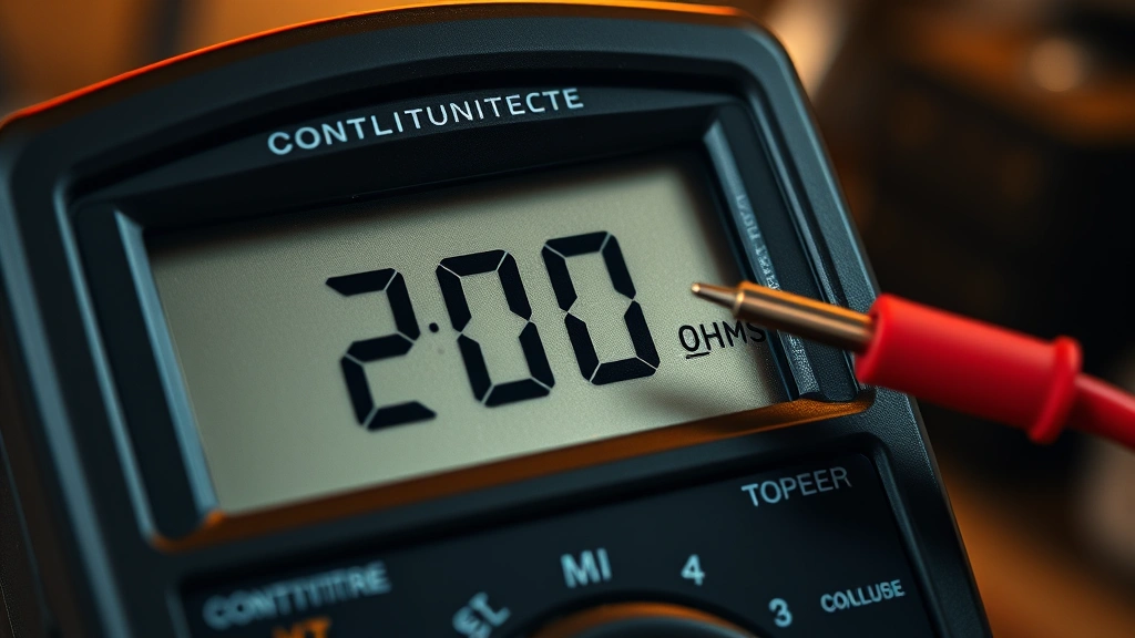
The multimeter’s continuity function measures resistance using the ohm scale (Ω symbol). When testing continuity, the multimeter sends a small voltage through the component and measures the resistance. Most digital multimeters also produce an audible beep when continuity is detected, making it easy to identify a continuous path without constantly looking at the display.
Understanding continuity is crucial for several reasons. It helps you identify broken wires, failed components, faulty switches, and poor connections. This knowledge directly supports other multimeter skills, such as when you’re checking a battery with a multimeter or learning to check amps using a multimeter.
Digital Multimeter Features and Settings
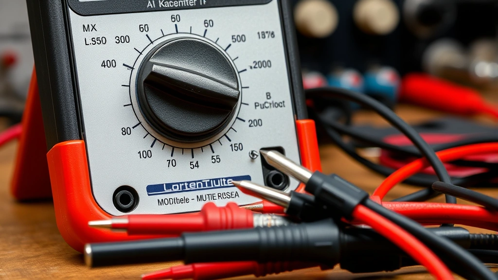
Before you can test continuity, you need to familiarize yourself with your digital multimeter’s layout and features. Most modern digital multimeters share similar designs and functions, though specific button placements and display types may vary slightly between manufacturers.
Key Components of a Digital Multimeter:
- Display Screen: Shows numerical readings and symbols indicating the measurement type
- Rotary Dial/Selector Knob: Rotates to select different measurement modes (voltage, resistance, continuity, amperage)
- Input Jacks: Typically includes a common (COM) jack and separate jacks for different measurement types
- Test Leads: Red and black probes that connect to the input jacks and make contact with the circuit
- Function Buttons: Some multimeters have dedicated buttons for specific functions like continuity or resistance
- Backlight: Helpful feature for working in dimly lit areas
The continuity setting is typically represented by a symbol that looks like a sound wave or diode symbol (⊳| or ◯~) on the rotary dial. Different multimeter brands may use slightly different symbols, so consult your user manual if you’re unsure. Some advanced multimeters have dedicated continuity buttons that automatically activate the function when pressed.
When you select the continuity mode, the multimeter’s internal circuitry generates a small test voltage (usually between 1.5 and 9 volts, depending on the meter) and measures the resistance between the two test points. This low voltage is safe for testing most electronic components and is specifically designed to avoid damaging sensitive circuits.
Step-by-Step Continuity Testing Procedure
Now let’s walk through the actual process of testing continuity with your digital multimeter. Following these steps carefully will ensure accurate results and safe operation.
Step 1: Prepare Your Equipment
Start by ensuring your multimeter is in good working condition. Check that the test leads are properly connected—the black probe should be in the COM (common) jack, and the red probe should be in the VΩmA (voltage/ohms/milliamps) jack. Verify that the leads are not damaged, cut, or worn, as damaged leads can produce inaccurate readings.
Step 2: Turn Off Power
This is the most critical safety step. Always disconnect power to the circuit or component you’re testing before proceeding. Turn off switches, unplug devices, or disconnect batteries. Testing continuity on a live circuit can damage your multimeter and create safety hazards. If you’re working on a vehicle, disconnect the negative battery terminal. For household circuits, switch off the breaker and verify with a voltage tester that power is actually off.
Step 3: Select Continuity Mode
Rotate the multimeter’s dial to the continuity setting. This is usually marked with a sound wave symbol or diode symbol. Some multimeters have an auto-ranging feature that automatically selects the appropriate resistance range when you select continuity mode. If your multimeter requires manual range selection, start with the lowest resistance range (typically 200Ω or less).
Step 4: Touch the Test Leads to the Component
With the multimeter set to continuity mode, touch the black test lead to one end of the component or wire you’re testing, and touch the red test lead to the other end. Make firm contact with both points to ensure accurate readings. The order doesn’t matter—touching black first or red first produces the same result.
Step 5: Observe the Results
If continuity exists (a complete circuit path), the multimeter will display a low resistance value (typically 0 to 1 ohm) and produce an audible beep. The beeping sound is your confirmation that current can flow through the component. If no continuity exists (an open circuit), the display will show “1” or “OL” (overload/open line), and you won’t hear a beep. Some multimeters also display “∞” (infinity) to indicate an open circuit.
Step 6: Remove the Test Leads
After you’ve obtained your reading, remove both test leads from the component and return the multimeter dial to a neutral position or turn off the device. This prevents accidental damage if the multimeter is bumped or dropped.
Common Applications for Continuity Testing
Continuity testing has numerous practical applications in home repair, automotive work, and electronics projects. Understanding these real-world uses helps you recognize situations where continuity testing is the right diagnostic tool.
Testing Electrical Wiring and Cables
One of the most common applications is testing whether a wire or cable is broken or intact. If you suspect a wire is damaged inside its insulation, continuity testing can quickly confirm your suspicion. Simply disconnect the wire at both ends, touch one test lead to each end, and check for continuity. A continuous reading indicates an intact wire, while no continuity suggests a break somewhere along the length.
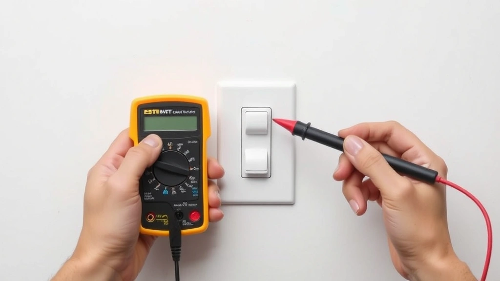
Diagnosing Switch Failures
Light switches and other electrical switches can fail over time. When a switch is in the ON position and has continuity, electricity can flow through it. When it’s in the OFF position, there should be no continuity. If a switch shows continuity in both positions, it’s likely stuck in the ON position and needs replacement. Conversely, if it shows no continuity in either position, the switch is completely broken.
Checking Fuses
A blown fuse will have no continuity, while a good fuse will show continuity across its terminals. This is a quick way to test whether a fuse needs replacement without having to visually inspect it. This skill is particularly useful in automotive work, where blown fuses are common issues related to DIY car repairs.
Testing Heating Elements and Resistors
Components like heating elements, light bulb filaments, and resistors should show continuity when they’re functioning properly. A heating element with no continuity indicates it’s burned out and needs replacement. This applies to appliances like ovens, water heaters, and electric space heaters.
Verifying Electrical Connections
When you’re building a circuit or connecting wires in a home electrical project, continuity testing verifies that all connections are solid. Test from one end of your circuit to the other to confirm that electricity can flow through your entire installation. This is essential before you energize the circuit with power.
Identifying Ground Faults
In some cases, continuity testing can help identify whether a component is properly grounded. A grounded component should show continuity between its case or frame and the ground wire. If this continuity is missing, you may have a grounding problem that needs correction.
Safety Precautions and Best Practices
Working with electrical components requires careful attention to safety. Following these precautions protects both you and your equipment.
Always Disconnect Power First
This cannot be overstated. Never test continuity on a live circuit. Testing a powered circuit can damage your multimeter, cause electrical shock, or create dangerous arcs. If you’re unsure whether a circuit is powered, use a non-contact voltage tester or voltage meter to verify that power is off before proceeding with continuity testing.
Use Proper Personal Protective Equipment
Wear safety glasses when working with electrical components. If you’re working in a location with potential flying debris or chemical hazards, wear appropriate protective gear. While continuity testing itself is low-risk once power is disconnected, the surrounding work environment may present other hazards.
Inspect Test Leads Regularly
Damaged test leads can produce inaccurate readings or create safety hazards. Before each use, visually inspect the leads for cuts, cracks, or exposed wiring. If you find damage, replace the leads immediately. Quality test leads are inexpensive insurance against equipment failure and personal injury.
Know Your Multimeter’s Specifications
Different multimeters have different maximum voltage and current ratings. Consult your multimeter’s user manual to understand its limitations. Using a multimeter outside its rated specifications can damage the device or produce inaccurate results. For example, some multimeters shouldn’t be used to test circuits with voltages exceeding 600V.
Test Your Multimeter’s Continuity Function
Before relying on your multimeter for important testing, verify that its continuity function works correctly. Touch the two test leads together (they should make a beeping sound and display 0Ω). Then separate them (you should hear no beep and see an open circuit indication). This quick verification ensures your multimeter is functioning properly.
Avoid Testing Sensitive Electronics
The small voltage generated by a multimeter’s continuity function is generally safe for most components, but some sensitive electronics like computer chips and microcontrollers can be damaged by this test voltage. If you’re working with advanced electronics, consult the component’s datasheet or a professional technician before testing continuity.
Troubleshooting and Interpreting Results
Understanding what your multimeter’s continuity readings mean is essential for accurate diagnosis. Let’s examine various scenarios and what they indicate.
The Beep and Zero Reading: Continuity Confirmed
When your multimeter beeps and displays 0Ω (or a very low value like 0.1Ω to 1Ω), you have confirmed continuity. This means there is a complete, unbroken electrical path between your two test points. The component or wire is functioning properly in terms of electrical conductivity. In the case of switches, a beep when the switch is ON indicates the switch is working correctly.
No Beep and Infinite Resistance: No Continuity
When the multimeter displays “1,” “OL,” or “∞” with no beeping sound, there is no continuity. This indicates an open circuit—an incomplete electrical path. This is the expected result when testing a switch in the OFF position, a blown fuse, or a broken wire. If you were expecting continuity but got this result, you’ve found your problem.
Unexpected High Resistance Values
Sometimes you may see a reading between 0Ω and infinity, such as 10Ω, 50Ω, or higher. This indicates partial continuity or a corroded/dirty connection. While some current can flow, the resistance is higher than ideal. This often happens with corroded battery terminals, dirty switch contacts, or partially broken wires. In most cases, these connections should be cleaned or repaired to restore proper function. For applications requiring very low resistance (like ground connections), these readings may indicate a problem.
Inconsistent Readings
If you test the same component multiple times and get different results, you likely have a intermittent connection. This could be caused by a loose wire, a corroded connection, or a component that’s failing. Intermittent connections are particularly problematic because they’re hard to diagnose but can cause equipment to malfunction unpredictably. Try wiggling the test leads or the component slightly while testing to see if the reading changes.
Testing Diodes and Semiconductors
Some digital multimeters have a dedicated diode testing mode separate from continuity mode. This is important because diodes are designed to allow current flow in one direction only. A diode tested in the forward direction should show low resistance (continuity), while testing in the reverse direction should show high resistance (no continuity). Don’t use the standard continuity mode for diode testing—use the diode-specific mode if your multimeter has one.
When you’re learning how to charge a car battery or performing other automotive maintenance, understanding these readings becomes even more important for diagnosing electrical problems.
FAQ
What’s the difference between continuity testing and resistance testing?
Continuity testing is a specific application of resistance measurement that focuses on whether a complete electrical path exists. The multimeter beeps to alert you to continuity, making it quick and convenient. Resistance testing measures the actual resistance value in ohms, giving you more detailed information about the component. You can use the resistance mode (Ω setting) to get precise resistance readings for components that should have specific resistance values.
Can I test continuity on a live circuit?
No, absolutely not. Always disconnect power before testing continuity. Testing on a live circuit can damage your multimeter, give inaccurate readings, and create serious safety hazards including electrical shock. If you need to test a live circuit, use a proper voltage meter or non-contact voltage tester first to verify that power is present, then turn off the power before proceeding with continuity testing.
Why does my multimeter show a low resistance value instead of 0Ω for a good wire?
Wires and components always have some small amount of resistance due to the material they’re made from. Copper wire, for example, has very low but measurable resistance that increases with length. A reading of 0.1Ω to 1Ω for a wire is perfectly normal and indicates good continuity. The multimeter’s internal resistance and test lead quality also contribute to these small readings. As long as the resistance is in the low range and the multimeter beeps, continuity is confirmed.
How do I test continuity on a wire inside a wall?
Testing continuity on in-wall wiring requires careful planning. First, turn off power to the circuit using the breaker. At one end of the circuit (like at an outlet), disconnect the wire. Then, at the other end (like at the breaker panel), touch your multimeter test leads to the two ends of the wire you’re testing. This allows you to test the entire length of the wire without having to physically access it. However, if the wire is broken inside the wall, you’ll need to call a professional electrician to locate and repair it.
What should I do if my multimeter shows no continuity when I expect there to be continuity?
First, verify that your multimeter itself is working by touching the two test leads together—you should hear a beep. If the multimeter beeps when you touch the leads together but shows no continuity for your component, the component is likely broken or disconnected. Check for loose connections, corroded terminals, or damaged components. If you’re testing a switch, verify that it’s in the correct position. Try cleaning the contact points with a pencil eraser or electrical contact cleaner and test again.
Is it safe to test continuity on battery-powered devices?
Yes, testing continuity on battery-powered devices is generally safe. However, you should still disconnect the battery before testing to avoid any potential issues. The multimeter’s continuity test voltage is very low and won’t damage most components, but disconnecting the battery ensures that you’re only testing the component itself without any interference from the device’s internal power supply.
Can I use continuity testing to find a short circuit?
Continuity testing can help identify some types of shorts, but it’s not the primary tool for this purpose. A short circuit occurs when two wires or components that shouldn’t be connected electrically come into contact, creating an unintended path for current. You might use continuity testing to verify that two wires aren’t touching each other when they shouldn’t be, but finding the location of a short in complex circuits usually requires more sophisticated diagnostic equipment and techniques. For electrical work, consult the National Electrical Code (NEC) guidelines or contact a licensed electrician.
What multimeter settings should I use for different components?
For most continuity testing, the dedicated continuity mode (⊳| symbol) is ideal because it provides audible feedback. For more precise resistance measurements, use the Ω (ohms) setting and manually select the appropriate range based on the expected resistance. For voltage measurements, use the V setting (AC or DC depending on your circuit). For current measurements, use the A (amps) setting. Consult your multimeter’s manual for specific guidance on your particular model.